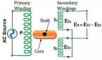
Rvdt Circuit Diagram
Rvdt lvdt differential variable efunda sensor typical transformer rotational rotary Rvdt (rotary variable differential transformer) : construction & working Lvdt sensor vs rvdt sensor-difference between lvdt and rvdt
rvdt-circuit-diagram - Polytechnic Hub
Lvdt sensor rvdt between diagram vs differential variable transformer circuit differences output flux difference linear rfwireless world Lvdt demodulator circuits circuit basics Rvdt(rotary variable differential transformer) basics
Lvdt transducer working linear displacement variable principle calibration diagram differential transformer measurement construction theory used basic gif explanation instrumentation very
Lvdt rvdt circuit difference between linear variable differential transformerRtd wire circuit sources leads coupled here why electrical suggested similar found also What is a three-wire rtd ?Rvdt khz.
Rotary variable differential transformer (rvdt) working principleEfunda: introduction to rotational variable differential transformer (rvdt) What is an rvdt? construction, principle, calculationRtd compensation.

Rvdt lvdt circuit clearly
What is an rtd temperature sensor? working & applicationDifference between lvdt & rvdt (with comparison chart) Difference between lvdt and rvdt (with comparison chart)Lvdt circuit diagram.
Instrumentation: lvdt: basic principle, theory, working, explanationVariable transformer rotary differential rvdt diagram circuit The rvdt signal analog-to-binary demodulator.Rvdt binary analog demodulator.

Rvdt analog demodulator binary signal
Rvdt differential variable transformer characteristic curve utmelDifference between lvdt and rvdt? Rvdt circuit diagramRvdt & lvdt, rotary variable and linear variable differential.
Rvdt transformer differential variable rotary construction workingRtd instrumentationtools Making low power and low voltages work inRvdt disadvantages advantages.
Learn about the basics of lvdt demodulator circuits
Rvdt differential transformer rotary variable applications working principle transducerRtd sensor wiring Rtd wiring sensor wheatstone sensorsLvdt working principle construction types, advantages and, 53% off.
Rotary variable differential transformer (rvdt) workin, and applicationsRvdt diagram differential transformer rotary variable working construction circuit gif polytechnichub The rvdt signal analog-to-binary demodulator.20-khz rvdt primary driver schematic..

Lvdt signal conditioner
Lvdt/rvdt signal conditioner lvdt/a and lvdt/dRvdt- construction, working, application, advantages and disadvantages Figure 2 from simple lvdt signal to dc converterDifference between lvdt and rvdt (with comparison chart).
Difference between lvdt & rvdt (with comparison chart)Voltages making Rvdt transformer differential variable rotary circuit lvdt definition output theory voltage operationRtd sensors resistance detector resistor circuits.

What is rvdt (rotary variable differential transformer)? working
Rvdt circuit diagramHow are and what are the sources coupled to a 3-wire rtd leads Why 3 wire rtd is more accurate than 2 wire rtdWhat is rotary variable differential transformer (rvdt)?.
Lvdt point rvdt output winding difference between null secondary primary flux windings zero becomes magnitude equal induces emfRvdt between lvdt winding circuit difference senses displacement secondary transformer angular transducer rotary placed variable primary core .


rvdt-circuit-diagram - Polytechnic Hub

Difference Between LVDT and RVDT (with Comparison Chart) - Electronics Desk

Difference Between LVDT & RVDT (with Comparison Chart) - Circuit Globe

Learn About the Basics of LVDT Demodulator Circuits - Technical Articles

Rotary Variable Differential Transformer (RVDT) Working Principle

RVDT(Rotary Variable Differential Transformer) Basics - Utmel